Develop Pico programs on Raspberry Pi or Linux
- Development environment setup
- Use CMake to manage and build projects
- Use picotool to download binaries to Pico
- Use minicom to acquire printf messages from Pico
- Debug Pico programs
Development environment setup
-
Download
pico_setup.shsudo apt install wget wget https://raw.githubusercontent.com/raspberrypi/pico-setup/master/pico_setup.sh -
Directly run
pico_setup.sh. N.B. The absolute path of the current directory should not contain white spaces.
During the the setup, the following dependencies will be installed
gcc-arm-none-eabi: C/C++ compiler for embedded ARM chips using Cortex-M and Cortex-R processors.gdb-multiarch: GDB that supports multiple target architectureslibftdi-dev: header files and static libraries for usinglibftdi, which is responsible for communication with EEPROM chips.libusb-1.0-0-dev: for programming USB applications.libjim-dev: Jim is an implementation of the Tcl language.libgpiod-dev: encapsulation of ioctl calls and data structures.
And the following tools provided by Pico SDK will also be built and installed:
picotools: Tools for interacting with RP2040/RP2350 devices in BOOTSEL mode and with binaries, such as uploading binaries to Pico.openocd(Open On-Chip Debugger): Used for starting a debugging session, to which the debugger GDB can connect.
Use CMake to manage and build projects
Example CMakeLists.txt for the hello-world target:
set(_target hello-world)
add_executable(${_target} hello-world.S)

# Enable UART output and disable USB output. With UART, we can debug Pico
# program and receive print messages via minicom.
pico_enable_stdio_usb(${_target} 0)
pico_enable_stdio_uart(${_target} 1)
# General additional output files from ELF firmware target, including UF2, bin,
# dis, hex and map files.
pico_add_extra_outputs(${_target})

target_link_libraries(${_target} pico_stdlib)
Configure and build the project:
mkdir pico-dev-build
cd pico-dev-build
cmake -DCMAKE_BUILD_TYPE=Debug -DPICO_BOARD=pico2_w ../pico-dev
make -j4 all
Use picotool to download binaries to Pico
- It should be run with
sudo. -
Load a program into the flash when Pico is in the
BOOTSELmode:sudo picotool load <filename.uf2>If Pico is in the application mode, execute
sudo picotool load -f <filename.uf2>, which will force Pico to reboot intoBOOTSELmode, then load the program to flash. - Enable Pico program to support communication via USB, so that we can use
picotoolto control the running mode of Pico.-
CMake configuration
# enable usb output, disable uart output
pico_enable_stdio_usb(${_target} 1)
pico_enable_stdio_uart(${_target} 0)
The standard USB connection is used for initial programming via the BOOTSEL mode or for basic serial communication (e.g., printf output), but not for interactive, step-through debugging. For program debugging, we need to use the UART mode.
pico_enable_stdio_usb(${_target} 0) pico_enable_stdio_uart(${_target} 1) -
In the source code, include the header file
stdio.hand callstdio_init_all()at the beginning ofmain.
-
- Reboot the device into application mode:
sudo picotool rebootorsudo picotool reboot -a - Reboot the device into BOOTSEL mode:
sudo picotool reboot -u
Use minicom to acquire printf messages from Pico
Receive messages from Pico via UART or USB:
sudo minicom -b 115200 -D /dev/ttyACM0
Debug Pico programs
Hardware and software preparation for debugging Pico programs
- Two alternatives of the mandatory hardware for debugging Pico on platforms, such as Linux, Windows, macOS, which do not have GPIOs to connect directly to UART or SWD (Serial Wire Debug).
- Use Raspberry Pi Debug Probe, which includes an RP2040 chip.
- Use another Pico or Pico 2 which runs the firmware
debugprobe.
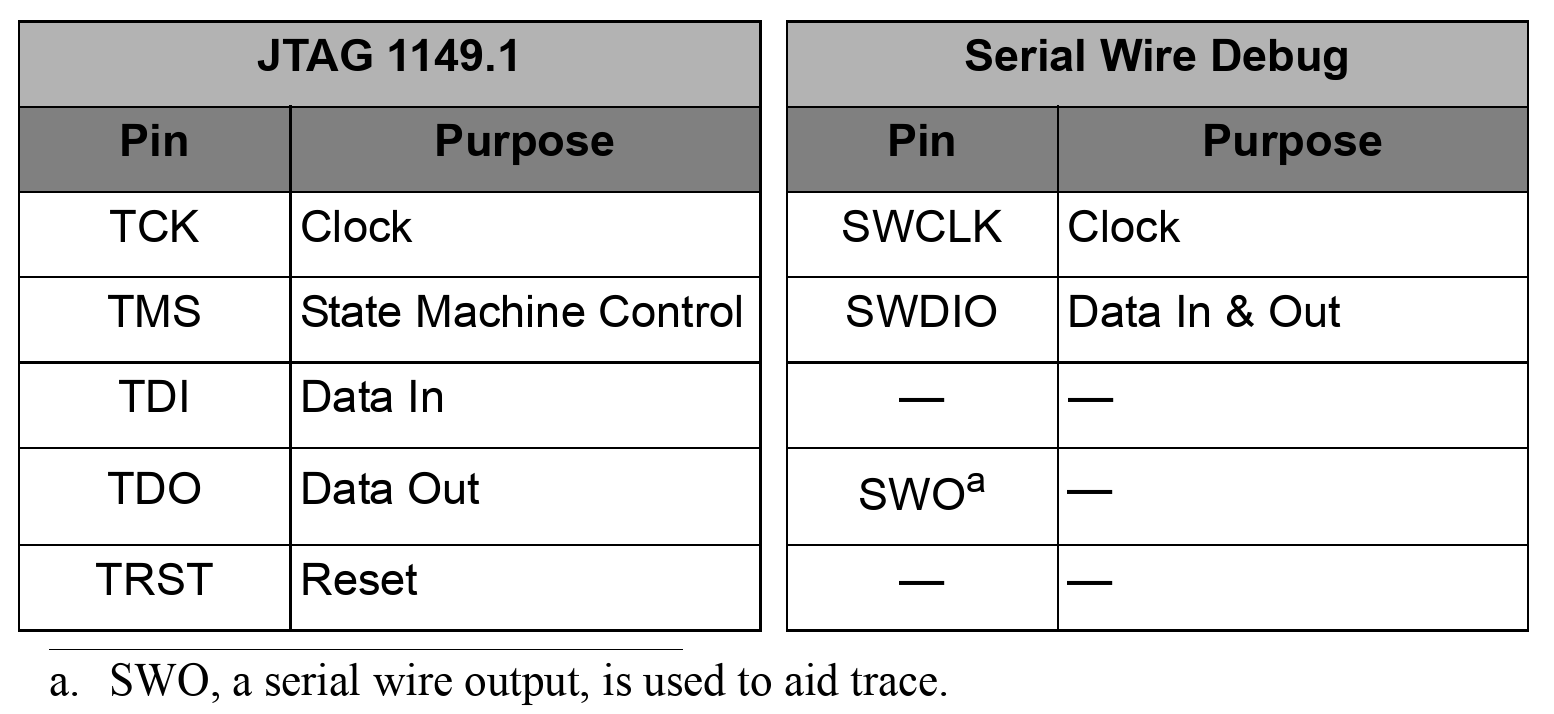
- Serial Wire Debug brings fully capable debug and trace facilities to MCUs such as ARM Cortex-M3 processors while keeping chip and tool costs low, yet leaving the greatest number of pins available for system I/O.
-
Comparison with SWD and the old JTAG debug interface.
-
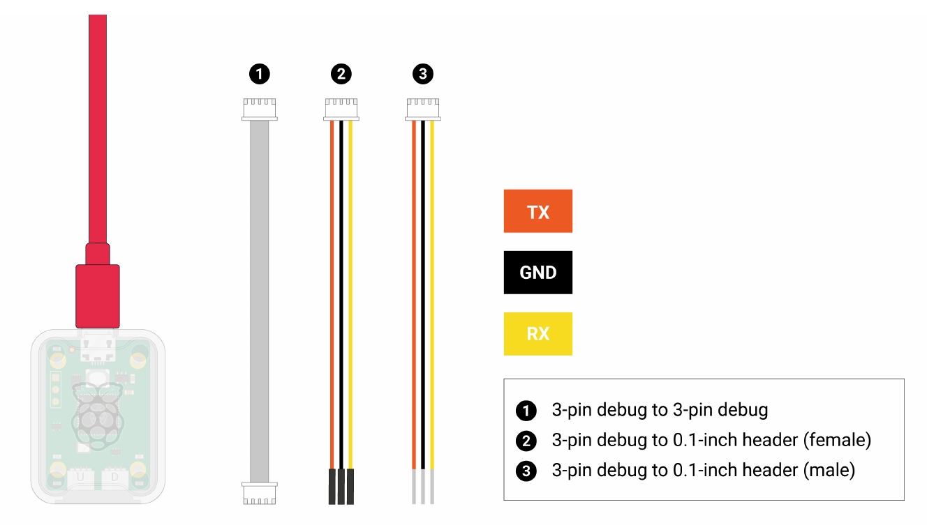
Hardware connection for debugging Pico
- RX on the debug probe connects to TX on Pico (Pin 1)
- TX on the debug probe connects to RX on Pico (Pin 2)
- GND on the debug probe connects to GND on Pico (Pin 3)
- Two USBs connect to PC.

- Install
openocd, which will be automatically installed when runningpico_setup.sh. - Install
gdb-multiarchon Linux orgdbon Raspberry Pi OS.
Procedures for debugging Pico programs
-
Enable UART for the program to be debugged by editing
CMakeLists.txt, where${_target}is the target name.pico_enable_stdio_usb(${_target} 0) pico_enable_stdio_uart(${_target} 1) -
Configure and build the project in the debug mode, so that debugging symbols will be written into the binary file.
cd pico-dev-build cmake -DCMAKE_BUILD_TYPE=Debug -DPICO_BOARD=pico2_w ../pico-dev make -j4 all -
Download the ELF file to Pico via
openocd.sudo openocd -f interface/cmsis-dap.cfg -f target/rp2350.cfg -c "adapter speed 5000" -c "program <target>.elf verify reset exit"After execute, the following message appears:
Open On-Chip Debugger 0.12.0+dev (2025-10-24-02:10)
Licensed under GNU GPL v2
For bug reports, read
        http://openocd.org/doc/doxygen/bugs.html
Info : [rp2350.cm0] Hardware thread awareness created
Info : [rp2350.cm1] Hardware thread awareness created
ocd_process_reset_inner
adapter speed: 5000 kHz
Info : Using CMSIS-DAPv2 interface with VID:PID=0x2e8a:0x000c, serial=E6647C74030E872F
Info : CMSIS-DAP: SWD supported
Info : CMSIS-DAP: Atomic commands supported
Info : CMSIS-DAP: Test domain timer supported
Info : CMSIS-DAP: FW Version = 2.0.0
Info : CMSIS-DAP: Interface Initialised (SWD)
Info : SWCLK/TCK = 0 SWDIO/TMS = 0 TDI = 0 TDO = 0 nTRST = 0 nRESET = 0
Info : CMSIS-DAP: Interface ready
Info : clock speed 5000 kHz
Info : SWD DPIDR 0x4c013477
Info : [rp2350.cm0] Cortex-M33 r1p0 processor detected
Info : [rp2350.cm0] target has 8 breakpoints, 4 watchpoints
Info : [rp2350.cm0] Examination succeed
Info : [rp2350.cm1] Cortex-M33 r1p0 processor detected
Info : [rp2350.cm1] target has 8 breakpoints, 4 watchpoints
Info : [rp2350.cm1] Examination succeed
Info : [rp2350.cm0] starting gdb server on 3333
Info : Listening on port 3333 for gdb connections
[rp2350.cm0] halted due to debug-request, current mode: Thread
xPSR: 0xf9000000 pc: 0x00000088 msp: 0xf0000000
[rp2350.cm1] halted due to debug-request, current mode: Thread
xPSR: 0xf9000000 pc: 0x00000088 msp: 0xf0000000
Info : RP2350 rev 2, QSPI Flash win w25q32fv/jv id = 0x1640ef size = 4096 KiB in 1024 sectors
Info : RP2xxx ROM API function FC @ 3711
** Programming Started **
Info : Padding image section 2 at 0x10003e24 with 220 bytes (bank write end alignment)
Warn : Adding extra erase range, 0x10003f00 .. 0x10003fff
** Programming Finished **
** Verify Started **
** Verified OK **
** Resetting Target **
shutdown command invoked
The above two files on the command line,
interface/cmsis-dap.cfgandtarget/rp2350.cfg, can be found in/usr/local/share/openocd/scriptsafter installingopenocd.A script
send-elf.shhas been created in thepico-dev/scriptsfolder to assist typing the above command line. Run it assend-elf.sh <elf-file>. -
Start
openocdin server mode, which listens to the port3333on localhost.sudo openocd -f interface/cmsis-dap.cfg -f target/rp2350.cfg -c "adapter speed 5000"The following message appears:
Open On-Chip Debugger 0.12.0+dev (2025-10-24-02:10)
Licensed under GNU GPL v2
For bug reports, read
        http://openocd.org/doc/doxygen/bugs.html
Info : [rp2350.cm0] Hardware thread awareness created
Info : [rp2350.cm1] Hardware thread awareness created
ocd_process_reset_inner
adapter speed: 5000 kHz
Info : Listening on port 6666 for tcl connections
Info : Listening on port 4444 for telnet connections
Info : Using CMSIS-DAPv2 interface with VID:PID=0x2e8a:0x000c, serial=E6647C74030E872F
Info : CMSIS-DAP: SWD supported
Info : CMSIS-DAP: Atomic commands supported
Info : CMSIS-DAP: Test domain timer supported
Info : CMSIS-DAP: FW Version = 2.0.0
Info : CMSIS-DAP: Interface Initialised (SWD)
Info : SWCLK/TCK = 0 SWDIO/TMS = 0 TDI = 0 TDO = 0 nTRST = 0 nRESET = 0
Info : CMSIS-DAP: Interface ready
Info : clock speed 5000 kHz
Info : SWD DPIDR 0x4c013477
Info : [rp2350.cm0] Cortex-M33 r1p0 processor detected
Info : [rp2350.cm0] target has 8 breakpoints, 4 watchpoints
Info : [rp2350.cm0] Examination succeed
Info : [rp2350.cm1] Cortex-M33 r1p0 processor detected
Info : [rp2350.cm1] target has 8 breakpoints, 4 watchpoints
Info : [rp2350.cm1] Examination succeed
Info : [rp2350.cm0] starting gdb server on 3333
Info : Listening on port 3333 for gdb connections
The
openocdprocess will occupy the terminal until it is closed by pressingCtrl+c.A script
start-openocd.shhas been created in thepico-dev/scriptsfolder to assist typing the above command line. Run it asstart-openocd.sh. -
After the
openocdserver starts, open another terminal and rungdb-multiarch(on Linux) orgdbon Raspberry Pi OS in another terminal.gdb-multiarch/gdb <target>.elfWe can see this message:
Reading symbols from hello-world.elf...In the interactive session of GDB:
-
Connect to the
openocdserver.target remote localhost:3333We should see the following message indicating GDB has connected to
localhost:3333and the program stops atuart_tx_wait_blocking.Remote debugging using localhost:3333 warning: multi-threaded target stopped without sending a thread-id, using first non-exited thread uart_tx_wait_blocking (uart=0x40070000) at pico-sdk/src/rp2_common/hardware_uart/include/hardware/uart.h:432 432 while (uart_get_hw(uart)->fr & UART_UARTFR_BUSY_BITS) tight_loop_contents(); -
Send
reset initto the remote monitoropenocdvia themonitorcommand in GDB.monitor reset initThis will reset Pico and run
openocd’s initialization sequence, then the program halts before themainfunction.We should see this message:
[rp2350.cm0] halted due to debug-request, current mode: Thread
xPSR: 0xf9000000 pc: 0x00000088 msp: 0xf0000000
[rp2350.cm1] halted due to debug-request, current mode: Thread
xPSR: 0xf9000000 pc: 0x00000088 msp: 0xf0000000
RP2xxx ROM API function FC @ 3711
available
The GDB commands in the previous two steps are written to the file
pico-dev/scripts/gdbinit. We can let GDB execute these commands directly when GDB starts by runninggdb -x pico-dev/scripts/gdbinit <elf-file>on the command line. -
Then we can set breakpoints and run the program. For example, set a breakpoint at the entrance of the
mainfunction:b mainWe should see this message:
Breakpoint 1 at 0x10000274: file pico-dev/source/hello-world.S, line 5.
Note: automatically using hardware breakpoints for read-only addresses.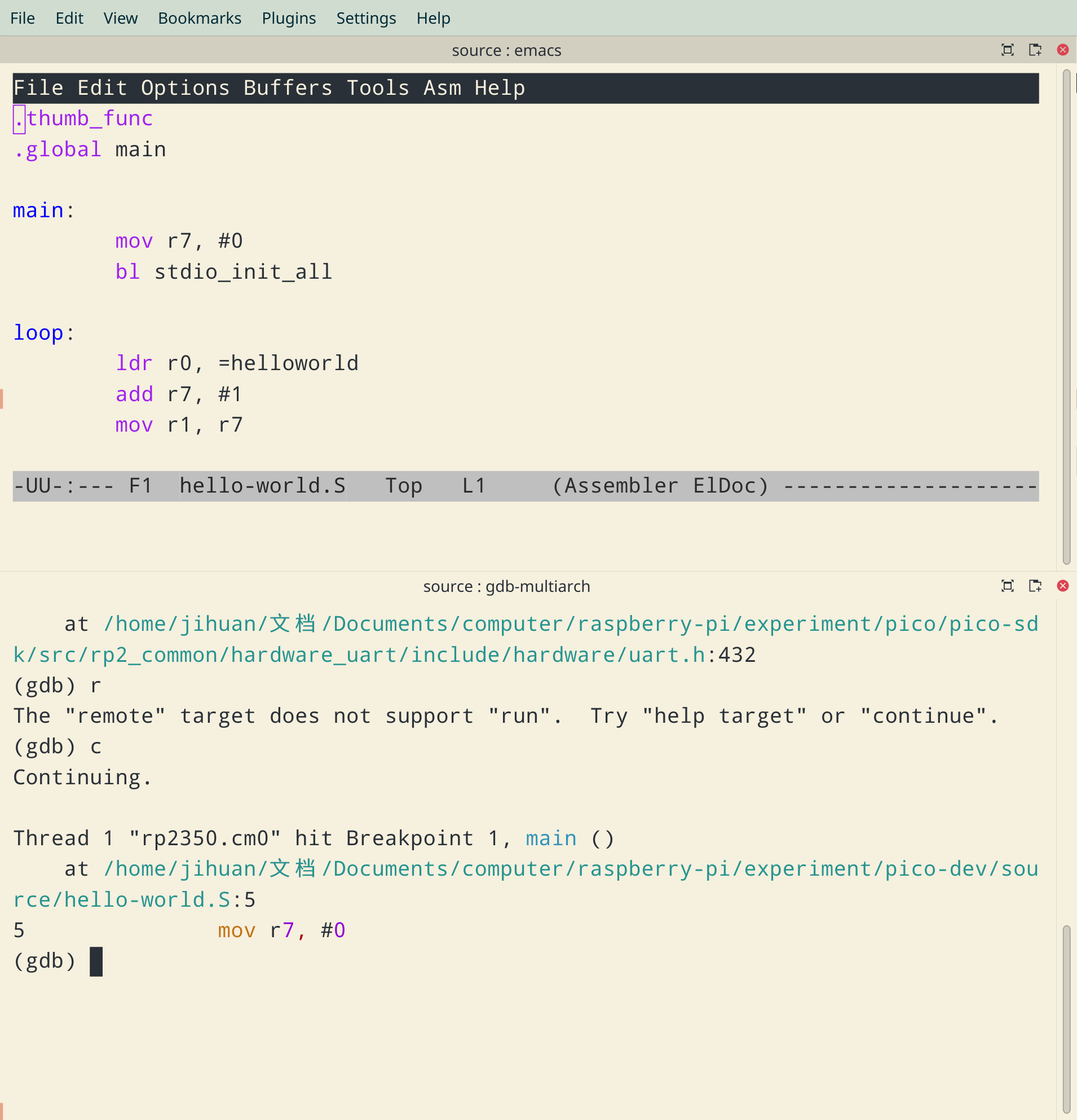
-
-
When stepping over the command
bl stdio_init_all, GDB gets stuck andopenocdserver repeatedly reports:rp2350.cm1] halted due to debug-request, current mode: Thread xPSR: 0x09000000 pc: 0x000000da msp: 0xf0000000This is caused by the fact that
stdio_init_allis not step-safe.Solution Set a breakpoint after
bl stdio_init_alland runcontinuein GDB to get there. For example, in thehello-worldtest case, we can break at line 9 inhello-world.S:b hello-world.S:9. -
After debugging is finished and exiting from
gdb, to let the program run normally, remove and reinsert the USB plug.
Usage of GDB
- Load a binary file:
load <target>.elf - After loading a binary file, we can run it until it stops at a breakpoint:
c - Single step the program:
s - Set a breakpoint at a function:
b <function-name> - Set a breakpoint at a line in a source file:
b <source-file>:<line-no> - List breakpoint information:
i b - Delete a break point:
d <breakpoint-no> - Display program source code:
l - Disassemble a function:
disassemble <function-name> - Examine memory contents:
x /<N>u<unit size>f<format> <address>, where<N>is the number of objects to display.uis used to specify the unit size and<unit size>can beb: byteh: half-word, i.e. 2 bytesw: word, i.e. 4 bytesg: giant word, i.e. 8 bytes
fis used to specify the display format and<format>can bet: binaryx: hexidecimald: decimali: instructions: string
<address>is the starting memory address.
-
List register contents:
i rr0 0xe000e434 -536812492 r1 0x10000275 268436085 r2 0x80808080 -2139062144 r3 0x100031a4 268448164 r4 0x100001d0 268435920 r5 0x88526891 -2007865199 r6 0x4f54710 83183376 r7 0x400e0014 1074659348 r8 0x43280035 1126694965 r9 0x0 0 r10 0x10000000 268435456 r11 0x62707361 1651536737 r12 0x4a6dc800 1248708608 sp 0x20082000 0x20082000 lr 0x1000018f 268435855 pc 0x10000274 0x10000274 <main> xpsr 0x69000000 1761607680 - Display help for a command:
h <command-name> - Interrupting the running program:
Control-c - Reset
gdb:mon reset init - Quit
gdb:q